Model & approach
- Reduce the CAD model to flow- and heat-relevant detail
- Represent engine, hydraulic and exhaust heat sources and cooling-air inlet conditions
- Evaluate velocity, pressure, temperature and the system-resistance curve

Project / Agricultural machinery
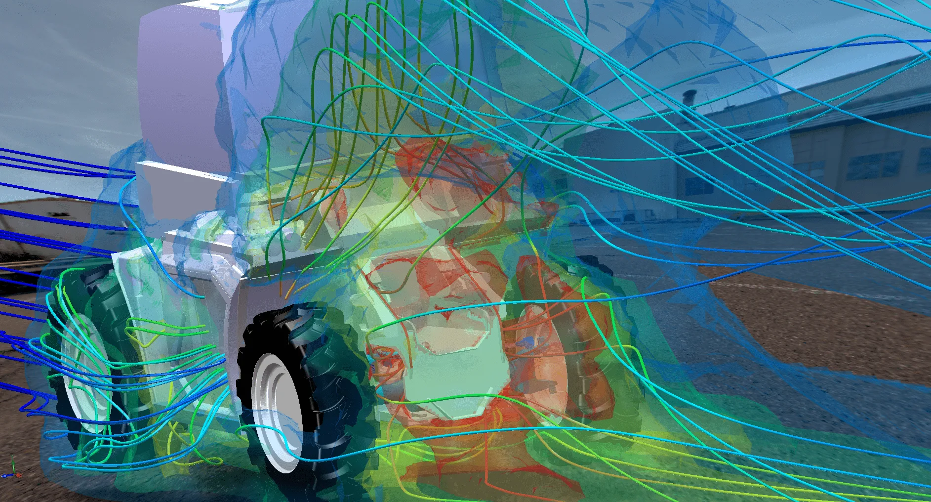
A full-vehicle model combined heat balance, airflow and system resistance to support preliminary cooling-component selection.
Engineering question
Model & approach
Boundary conditions
Results of the assessment
Engineering consequence
Context
Preliminary sizing of fans and fan drives applies to the operating conditions assessed.
 Off-highway
CFD simulation
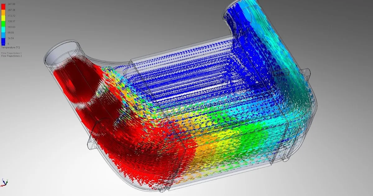
An unfavorable inlet geometry left large parts of the cooler matrix under-supplied. CFD exposed the recirculation and guided the geometry iterations.
View project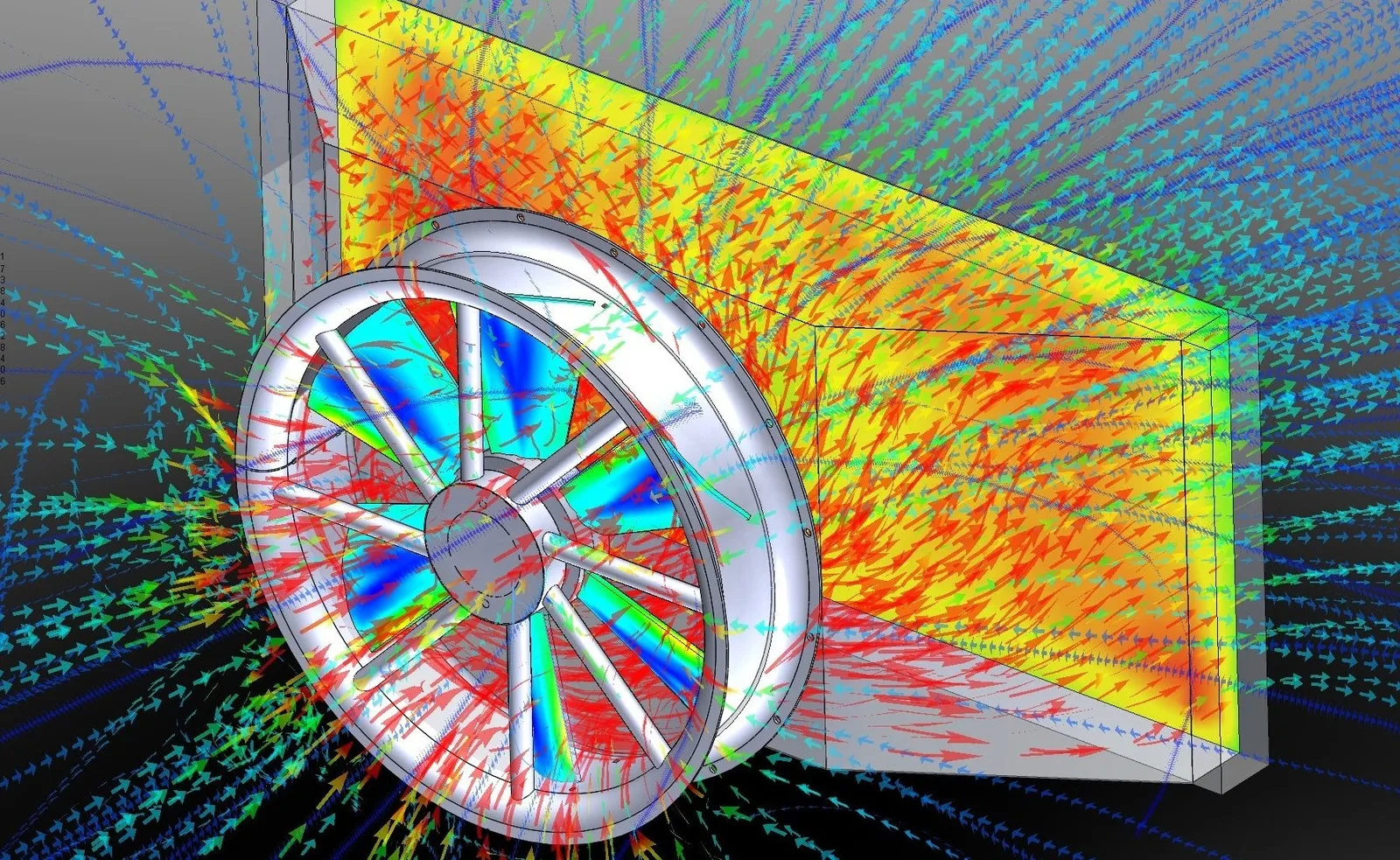 Off-highway
CFD simulation
Two design variants were compared in terms of airflow, pressure loss and transferable cooling duty.
View project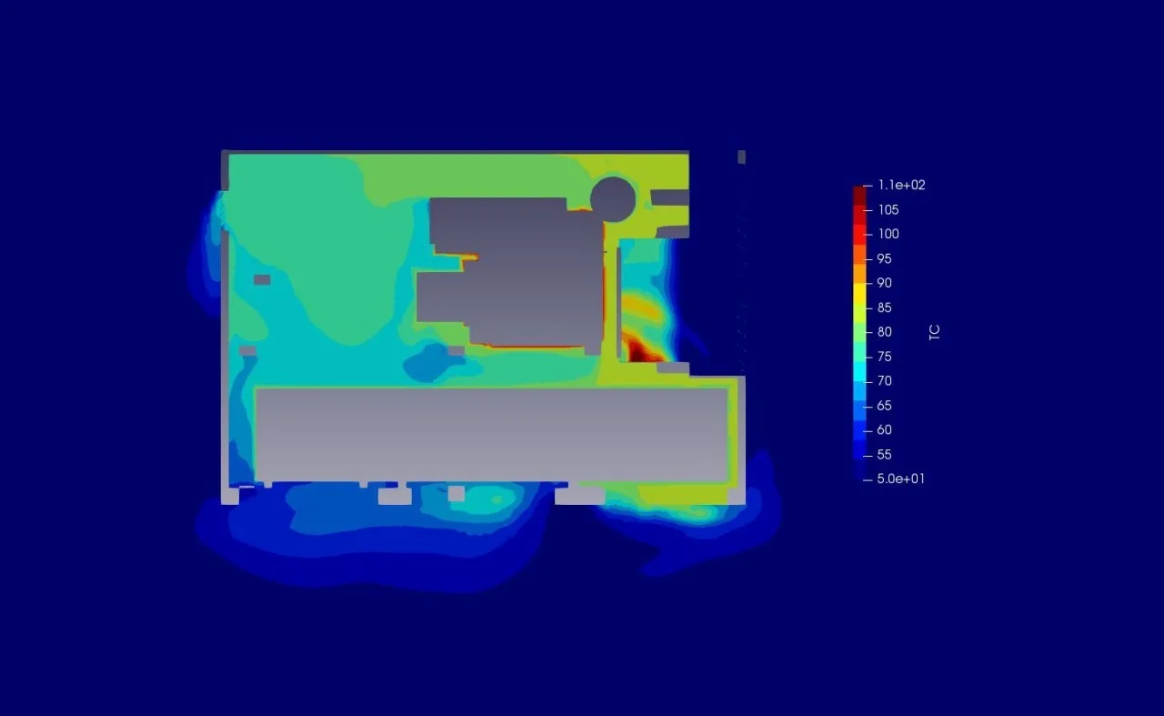 Off-highway
CFD simulation
Airflow, pressure loss and hot-air recirculation were assessed before a prototype of the enclosed machine was built.
View projectA similar question?