Model & approach
- Compare two oil-cooler and shroud geometries
- Assess inlet flow, pressure loss and heat transfer together
- Review the effects of inlet, fin and tube geometry on the design

Project / Thermal management
Two design variants were compared in terms of airflow, pressure loss and transferable cooling duty.
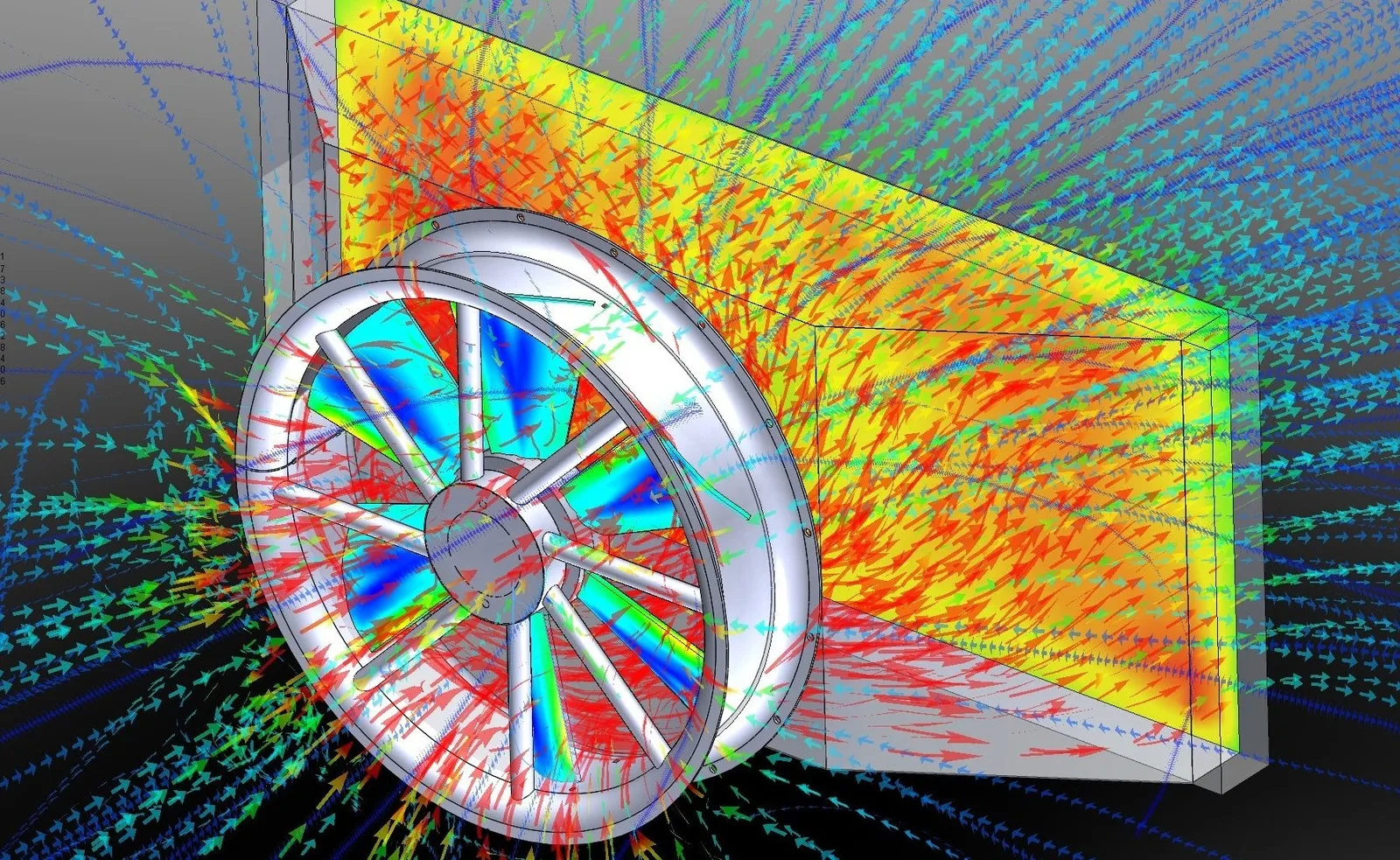
Engineering question
Model & approach
Boundary conditions
Results of the assessment
Engineering consequence
 Off-highway
CFD simulation
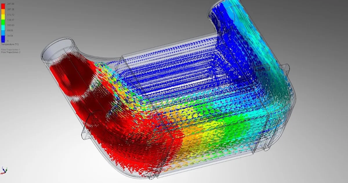
An unfavorable inlet geometry left large parts of the cooler matrix under-supplied. CFD exposed the recirculation and guided the geometry iterations.
View project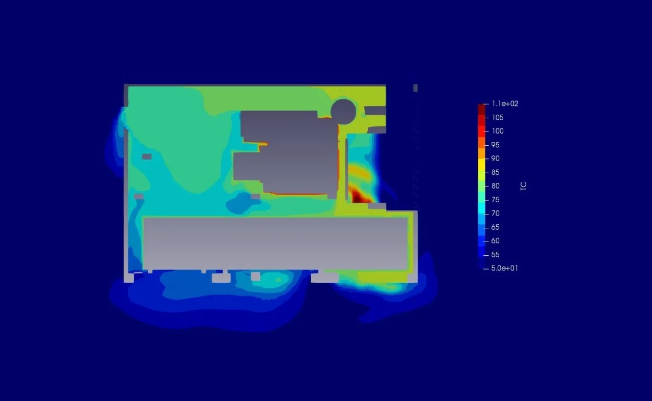 Off-highway
CFD simulation
Airflow, pressure loss and hot-air recirculation were assessed before a prototype of the enclosed machine was built.
View project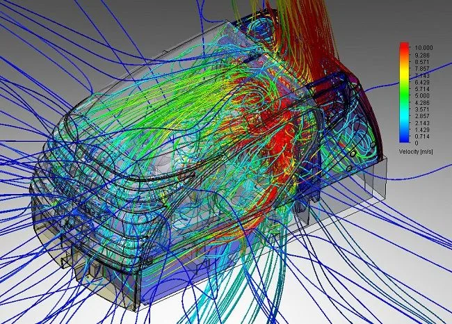 Off-highway
CFD simulation
A full-machine assessment combined inlet and outlet routing, pressure loss, component position and fan demand.
View projectA similar question?