Model & approach
- Model the complete installation and windbreak across several incident wind directions
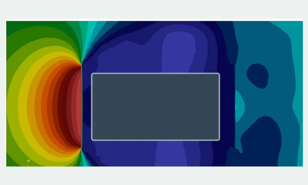
- Compare pressure at supply and discharge interfaces, wake structure and resultant wind force

Project study
External-flow CFD compared windbreak geometries and their influence on intake, discharge, local pressure and wind loading around a standalone technical installation.
Engineering question
Model & approach
Boundary conditions
Results of the assessment
Engineering consequence
 Process & plant engineering
CFD simulation
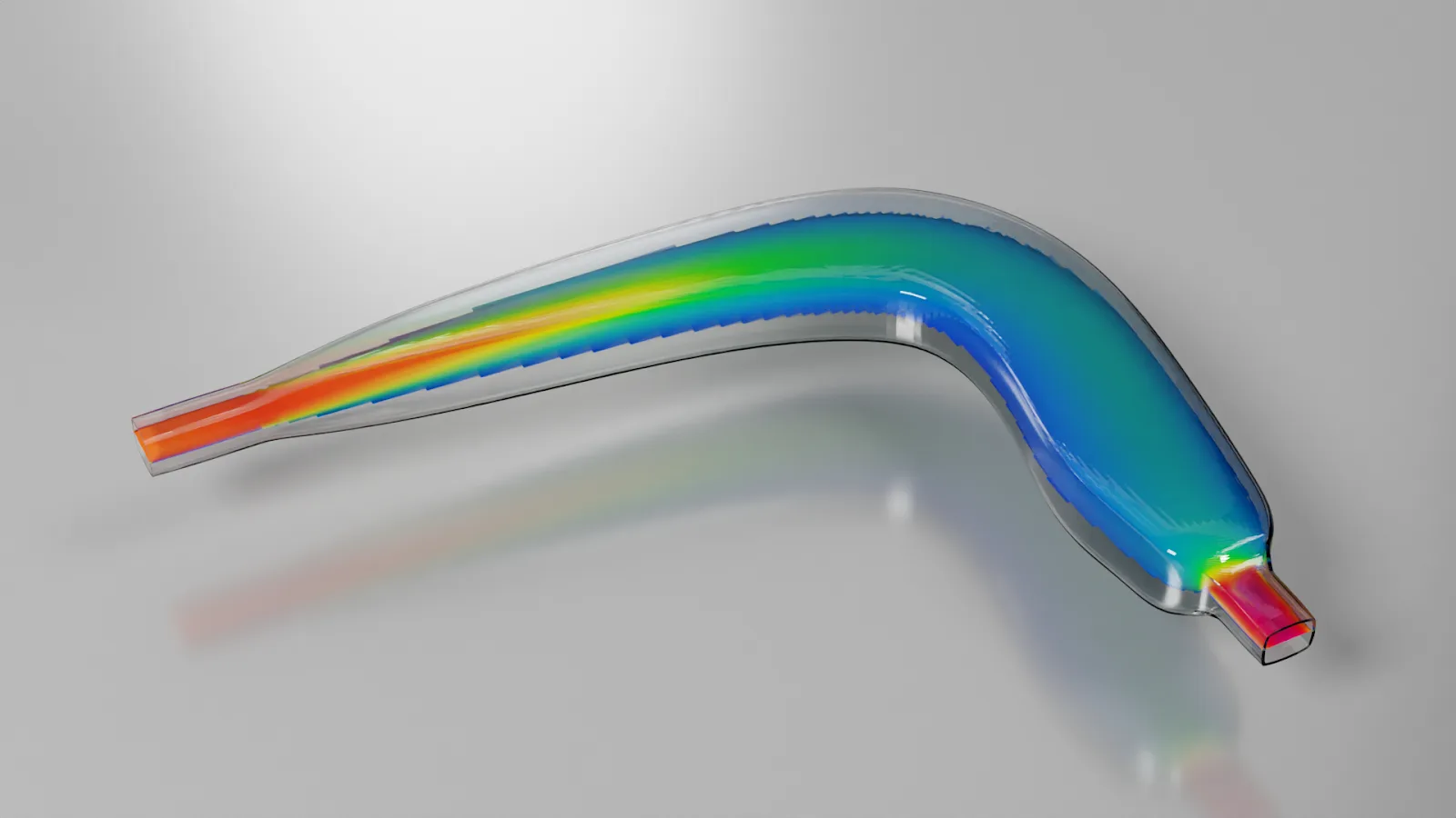
CFD and adjoint optimization were used to develop a compact flow turn within defined packaging constraints.
View project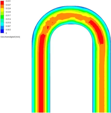 Process & plant engineering
CFD simulation
CFD assessed the form and orientation of separator baffles whose movement through pipe bends could impair stable operation.
View project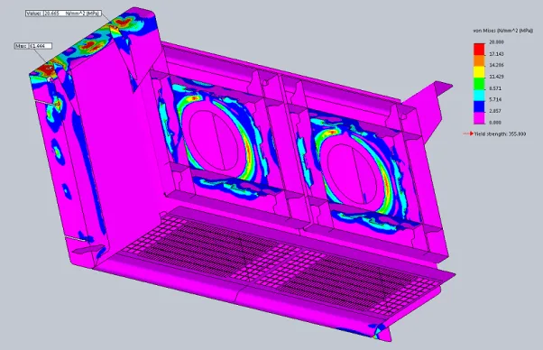 Process & plant engineering
FEA structural analysis
A finite-element model assessed the assembly, welded joints and support reactions across operating, exceptional and vibration load families.
View projectA similar question?